Achieving 2-Hour Fire Resistance Ratings with Cold-Formed Steel per ASTM E119
By Carlos Ferreira · April 7, 2026
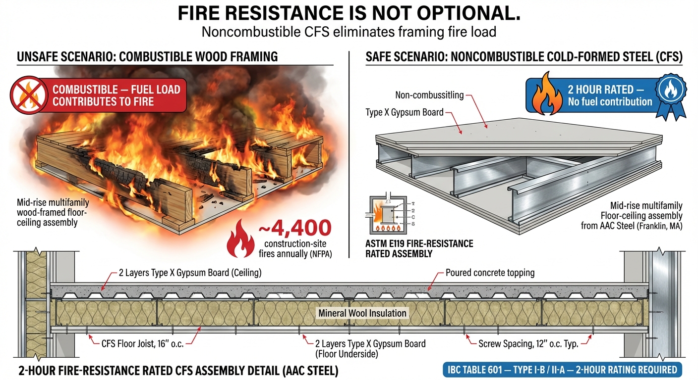
Achieving 2-Hour Fire Resistance Ratings with Cold-Formed Steel per ASTM E119
A Technical Guide to CFS Assembly Design, Test Methodology, and Code Compliance
AAC Steel Engineering | aacsteel.com — April 2026
Introduction
Fire resistance is not optional — it is the single most consequential life-safety parameter in multifamily and commercial building design. The International Building Code (IBC) mandates fire-resistance ratings for structural elements, floor-ceiling assemblies, and shaft enclosures based on construction type, occupancy group, and building height. For mid-rise multifamily projects — the fastest-growing segment in U.S. housing starts — achieving a 2-hour fire-resistance rating is frequently required under IBC Table 601 for Type I-B and Type II-A construction.
Cold-formed steel (CFS) framing provides a decisive advantage in fire-rated assembly design. Steel is classified as noncombustible per ASTM E136, meaning the framing itself contributes zero fuel load to a fire event. This is not a marginal benefit. NFPA data documents approximately 4,400 construction-site fires annually in the United States, and Willis Towers Watson reported over $400 million in wood-frame fire losses in 2023 alone. CFS eliminates the combustible-framing risk entirely.
At AAC Steel, we engineer and fabricate CFS assemblies in Franklin, MA, that routinely achieve 2-hour fire-resistance ratings through tested, listed configurations. This article provides a rigorous technical overview of the ASTM E119 test methodology, the specific assembly parameters that determine fire performance, and the code compliance pathway for specifying 2-hour CFS systems on your next project.
ASTM E119: Test Methodology and Acceptance Criteria
ASTM E119, formally titled "Standard Test Methods for Fire Tests of Building Construction and Materials," is the foundational fire test standard referenced by IBC Section 703.2. The test subjects a full-scale assembly specimen to a standardized time-temperature exposure curve and evaluates performance against three independent failure criteria.
The time-temperature curve prescribed by ASTM E119 is aggressive. Furnace temperature reaches 1,000°F (538°C) at 5 minutes, 1,700°F (927°C) at 60 minutes, and 1,850°F (1,010°C) at 120 minutes. For a 2-hour rating, the assembly must survive the full 120-minute exposure without failing any of the three acceptance criteria described in the table below.
Understanding these criteria is essential for assembly design. The structural integrity criterion governs load-bearing capacity under fire exposure — the assembly must sustain its design load throughout the test. The temperature transmission criterion limits heat transfer through the assembly; the unexposed surface average cannot exceed 250°F (139°C) above ambient, and no single thermocouple can exceed 325°F (181°C) above ambient. Finally, the hose stream test subjects the assembly to a 30-second application of water from a 2.5-inch hose at 30 psi immediately after furnace exposure, simulating real firefighting operations.
These criteria are not negotiable. An assembly that fails any single criterion — structural collapse, excessive heat transfer, or hose stream breach — does not receive the rating. This is why assembly design must be precise, and why AAC Steel specifies only UL-listed configurations with documented test data.
Table 1: ASTM E119 Acceptance Criteria for 2-Hour Fire-Resistance Rating
| Criterion | Requirement | Measurement Method | Failure Mode |
|---|---|---|---|
| Structural Integrity | Assembly sustains applied design load for full 120-minute exposure | Deflection monitoring; load maintained per test protocol | Structural collapse or inability to sustain load |
| Temperature Transmission | Unexposed surface avg. rise ≤250°F (139°C); single point rise ≤325°F (181°C) above ambient | Thermocouple array on unexposed surface per ASTM E119 §8.1 | Excessive heat transfer through assembly |
| Hose Stream | Assembly withstands 30-sec water application at 30 psi from 2.5-in. hose nozzle at 20 ft | Visual inspection for through-openings after water application | Water penetration or structural breach |
UL-Listed 2-Hour CFS Assemblies
Underwriters Laboratories (UL) maintains the most comprehensive database of fire-tested building assemblies in North America. For cold-formed steel (CFS) framing, several UL design numbers provide documented 2-hour fire-resistance ratings across the three primary assembly types required by the IBC.
Wall assemblies are typically documented under UL Design No. H514 (and related H-series designs). These assemblies achieve the 2-hour rating through multiple layers of Type X gypsum board on each face of the CFS stud wall, with specific requirements for stud gauge, spacing, screw patterns, and joint treatment. The gypsum layers serve as the thermal barrier, while the noncombustible CFS framing maintains structural integrity as the gypsum calcines during fire exposure.
Floor-ceiling assemblies fall under UL Design No. M527 (and related M-series designs). These configurations incorporate CFS joists, multiple gypsum layers on the ceiling side, resilient channel for thermal break and acoustic isolation, and concrete or gypsum-concrete topping on the floor side. The ceiling membrane is the critical fire barrier in these assemblies, and the resilient channel attachment detail is essential to maintaining membrane integrity under thermal deflection.
Shaft wall assemblies — required for elevator shafts, stairwell enclosures, and mechanical chases — are documented under UL Design Nos. D902 and D925 (and related D-series designs). These use C-H stud configurations with multiple gypsum liner panels and face layers, achieving the 2-hour rating in a thinner profile than back-to-back stud walls.
AAC Steel fabricates CFS framing packages for all three assembly types. Our shop drawings reference the specific UL design number, ensuring field installation matches the tested configuration exactly. This traceability from UL listing to shop drawing to installed assembly is the only reliable path to code-compliant fire resistance.
Table 2: Typical 2-Hour CFS Assembly Parameters by Type
| Parameter | Wall (UL H514-type) | Floor-Ceiling (UL M527-type) | Shaft (UL D902/D925-type) |
|---|---|---|---|
| CFS Framing | 3-5/8" to 6" studs, 20-16 ga., 16" o.c. | 8" to 12" joists, 16-14 ga., 16-24" o.c. | C-H stud, 25-20 ga., 24" o.c. |
| Gypsum Layers (Fire Side) | 2 layers 5/8" Type X each face | 2-3 layers 5/8" Type X ceiling | 2 layers 1" gypsum liner + 1 layer 5/8" Type X face |
| Gypsum Layers (Opposite) | 2 layers 5/8" Type X each face | N/A (floor topping above) | 1 layer 5/8" Type X (corridor side) |
| Resilient Channel | Not required (direct screw attach) | Hat channel or RC-1, 24" o.c. perpendicular to joists | Not required |
| Insulation | 3-1/2" mineral wool or fiberglass batts | Per UL listing; mineral wool or fiberglass | Typically none (air cavity) |
| Screw Spacing | 12" o.c. field, 8" o.c. edges (base layer); 12" o.c. field, 8" o.c. edges (face layer) | Per UL listing; typically 12" o.c. field, 8" o.c. edges | Per UL listing |
| Joint Treatment | Taped and finished per ASTM C840 | Taped and finished per ASTM C840 | Liner panels: butt joints staggered; face layer taped |
| Floor Topping | N/A | 1.5" normal-weight or lightweight concrete, or gypsum-concrete | N/A |
| Total Assembly Thickness | ~8" to 10" | ~14" to 18" (structure + ceiling membrane) | ~4" to 6" |
Critical Design Considerations for 2-Hour Assemblies
Achieving the fire-resistance rating on paper is straightforward — select a UL-listed assembly and specify it. Achieving it in the field requires attention to several details that frequently cause problems on multifamily projects.
Penetration firestopping is the most common source of fire-resistance failure in completed buildings. Every electrical box, conduit, pipe, and duct penetration through a fire-rated assembly must be firestopped with a UL-listed through-penetration firestop system (ASTM E814 / UL 1479). AAC Steel coordinates with MEP trades during the shop drawing phase to identify penetration locations and specify compatible firestop details.
Joint and gap treatment at assembly intersections — head-of-wall, wall-to-floor, wall-to-wall — requires listed joint systems per ASTM E1966 (UL 2079). The deflection gap at the top of CFS walls in multifamily construction must accommodate structural movement while maintaining the fire barrier. Slip-track and deflection connections must be designed to the UL listing requirements, not just structural criteria.
Screw pattern compliance is another area where field deviations create risk. The gypsum attachment pattern — screw spacing at edges versus field, screw type, and minimum edge distance — is specified in the UL listing. Overdriven screws that break the gypsum face paper reduce pull-through resistance and can compromise membrane integrity under fire exposure.
AAC Steel addresses these issues through detailed shop drawings that include fire-rating annotations, penetration coordination, and assembly section details keyed to the UL design number. Our Franklin, MA fabrication facility produces CFS framing to the exact gauge, depth, and punch pattern required by the listed assembly, eliminating field substitutions that could void the fire rating.
IBC Code Compliance Pathway
IBC Table 601 establishes minimum fire-resistance ratings by construction type. Type I-A requires 3-hour primary structural frame and 2-hour floor construction. Type I-B and Type II-A both require 2-hour primary structural frame and 2-hour floor construction. These are the construction types most commonly specified for mid-rise multifamily (4-7 stories) where CFS framing is structurally viable.
IBC Section 703.2 permits fire-resistance ratings to be established through three methods: ASTM E119 testing (Section 703.2.1), calculated fire resistance per Section 722 (Section 703.2.2), or prescriptive assemblies per IBC Table 722 series. For CFS assemblies, UL-tested configurations per ASTM E119 provide the most defensible and widely accepted compliance path. AHJs (Authorities Having Jurisdiction) are most comfortable with tested assemblies because the performance data is empirical, not calculated.
Section 703.4 addresses nonsymmetrical assemblies — assemblies with different configurations on each side. The fire-resistance rating applies to fire exposure from either side unless the assembly is specifically tested and listed for one-direction exposure only. This is particularly relevant for shaft walls, which are typically tested for fire exposure from the shaft side only.
AAC Steel provides UL listing references on all fire-rated assembly shop drawings, giving the design team and the AHJ a direct traceability path from the installed CFS framing to the tested assembly configuration. This documentation approach has streamlined inspections and approvals on dozens of multifamily projects across Massachusetts and New England.
Why CFS Outperforms Combustible Framing in Fire-Rated Construction
The noncombustibility of cold-formed steel (CFS) per ASTM E136 creates a fundamentally different fire risk profile compared to wood framing. In a fire-rated CFS assembly, the gypsum membrane provides the thermal barrier, and the steel framing behind it contributes zero fuel. If the gypsum membrane is breached — through a failed firestop, a construction defect, or fire exposure exceeding the rated duration — the CFS framing does not ignite. It may lose structural capacity at elevated temperatures (steel begins to lose strength above 1,000°F), but it does not add fuel to the fire.
Wood framing, by contrast, is combustible. Even in fire-rated wood-frame assemblies with multiple gypsum layers, a membrane breach exposes fuel. The approximately 4,400 construction-site fires per year documented by NFPA occur disproportionately in wood-frame buildings, and the $400 million in wood-frame fire losses reported by Willis Towers Watson in 2023 reflects the consequences of combustible framing during the construction phase — before fire-protection systems are operational.
For developers, architects, and engineers evaluating framing systems for mid-rise multifamily, the fire-resistance question is not just about achieving a code-required rating. It is about the margin of safety when things go wrong. CFS provides that margin. AAC Steel's fabrication capability in Franklin, MA ensures that the CFS framing delivered to your project is manufactured to the exact specifications required by the UL-listed fire-rated assembly.
Frequently Asked Questions
- What is the difference between a fire-resistance rating and a flame-spread rating?
- A fire-resistance rating (per ASTM E119) measures how long an assembly — wall, floor, or shaft — resists fire passage and structural collapse. It is expressed in hours (e.g., 2-hour). A flame-spread rating (per ASTM E84) measures how quickly flame spreads across a material surface. They are different tests evaluating different performance characteristics. CFS framing achieves noncombustible classification per ASTM E136, which is a material-level test distinct from both.
- Can CFS framing achieve a 2-hour fire-resistance rating without gypsum board?
- No. Steel framing alone does not provide fire resistance because steel loses structural capacity at elevated temperatures. The 2-hour fire-resistance rating is a property of the complete assembly — CFS framing plus gypsum board layers, insulation, screws, and joint treatment. All components must match the UL-listed configuration.
- Does AAC Steel provide fire-rated assembly documentation with shop drawings?
- Yes. AAC Steel references the applicable UL design number on all fire-rated assembly shop drawings. Our detailing team in Franklin, MA coordinates fire-rating requirements with the structural and architectural drawings to ensure the fabricated CFS framing matches the listed assembly.
- How do penetrations affect the 2-hour fire rating?
- Every penetration through a fire-rated assembly — electrical, mechanical, plumbing — must be firestopped with a UL-listed through-penetration firestop system tested per ASTM E814 (UL 1479). Unfirestopped or improperly firestopped penetrations void the fire-resistance rating at that location. AAC Steel coordinates penetration locations during the shop drawing phase.
- What construction types require 2-hour fire-resistance ratings?
- IBC Table 601 requires 2-hour fire-resistance ratings for primary structural frame and floor construction in Type I-A (3-hr frame), Type I-B, and Type II-A construction. These types are commonly specified for mid-rise multifamily buildings of 4-7 stories where CFS framing is structurally appropriate. AAC Steel has completed projects across all three construction types.
- Is CFS framing noncombustible?
- Yes. Cold-formed steel (CFS) is classified as noncombustible per ASTM E136. This means CFS framing contributes zero fuel load in a fire event, unlike wood framing. This noncombustibility is a material property of steel itself, not dependent on any coating or treatment.